
Home |
|
Index
Stuff Planes Forms Rebuilding Taper info |
|
I tie flies too, and got the idea, why not use the same bobbin technique, only on a bigger scale? It's not new, I found the same idea in The Complete Book of Sportfishing, (c:1988, AB Nordbok, Gothenburg, Sweden) The idea is, using a weighted bobbin (A.), to run the thread over the edge of the work bench. A support arm, made from a coat hanger, works great. It not only holds the thread away from the edge of the work bench, but also works as a shock absorber. I put a single spiral (B.) in the end of the coat hanger to allow me to insert the thread without having to push it though a hole. I attached a piece of fly line, with a weight on the front (C.), to the back of the bench and pull it over the rod toward me. ( I turn the rod counter clock wise, as you'd look at it from the left, wrapping away and over the top.) the weighted fly line will act as a break on the rod if I have to let go for some reason, keeping the thread from unwrapping. I pull the weighted bobbin close to the floor and wrap the rod until the bobbin is at the support arm. I repeat the process as long as needed. If I have to unwrap it's simple to reverse the direction. The weight of the bobbin keeps tension on the thread. When I'm done with the work I remove tension by putting my finger on top of the wrap and put the bobbin on the workbench. From there on it's no different then any other wrap. The weight for the bobbin is made of 1/2" washers, held in place by masking tape. |
||||
|
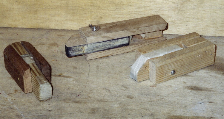
One more Design for a Binder
|
||||
|
||||
| click here for a photo |
Simple turning tool
 |
TOOL PARTS LIST
A. 4 small casters B. 1/4"x18" sc. 40 PVC C. 1/2" PVC pipe "guides" D. Masking tape "chuck" D1. Paper filler E. Work area F. Spring G. Pull cord H. Pull cord handle. |
| I didn't have room for a lath and I didn't want to put
out the $500 to over $1000 it could cost , so I designed a simple turning
tool. This tool allows me to turn ferrule stations accurately, though
it won't do many other jobs that a true lath would handle. The idea
goes back to colonial woodworking days.
It's fairly straight forward. The base is a 2"x4" about 16" long. attached to the base are two pair of casters, each pair facing each other about 1/16" apart. The main section is a piece of 1/4" (or 1/2") PVC Schedule 40 pipe, about 18" long.. Get the 1/4" if you can find it. If not go with the 1/2". The 4 guides are simply the next larger size pipe. Shim them in place and make sure they can't slip. You can glue them or tap and screw them, just make sure the screw doesn't go beyond the inside wall of your tube. The closer they fit, the better the tool will work. But remember there has to be a small amount of clearance between the casters and the guides, or there will be friction and you don't want that. The inside of the working end of the tube is flared just a bit. The reason will become apparent. Power is applied by your free hand. I'm left handed so I've set mine up with the work on the left side. For right handers, just turn it around. The spring can be mounted anywhere. Use pulleys to turn the cord in the correct direction. (my spring is attached to the ceiling and comes down behind the tool then through a pulley, up and wraps around the tube three or four times.) Simply pull the cord to turn the tube. When you release pressure on the cord, the spring will turn the tube in the opposite direction. Using the tool is simple. Mount the tool in a vice or other non movable mount. Mark the depth of your ferrule on the rod section. Carefully wrap the section with the edge of the masking tape at that mark. Take your time and don't let the tape get any wrinkles in it. Nows where that flair at the end of the tube comes in. Build the tape up until it just fits in the end of the tube. End the tape just before the place you started the wrap on the rod section. This will keep the tape form having a "hump" in it. Slide the section, other end first, down the tube until the tape is wedged in the tube so that only the work is protruding. Now wrap a 1" strip of any kind of paper around the other end of the section until it too fit's snugly in the rear of the tube. It really doesn't have to be tight, It's to align the section in the center of the tube. Fold a piece of course sand paper around the work so it's ends are touching each other. Hold them between your thumb and forefinger. Start turning the tool with the other hand. Work both directions. Check your work often. (I frequently stop and run the back side of an X-acto knife along the work, cross ways to the sanding scratches. This will remove the bamboo quickly.) As you approach the final dimension, switch to finer grit sandpaper. I see the 6 edges start to disappear first. eventually I'll see the flats start to show scratches from the sandpaper. I'm getting close. I really start really looking at what I'm doing as I approach the final size. It's easy to go too far. By folding the sandpaper around the work, you can apply equal pressure along the entire surface, but look for low spots and areas that are out of alignment. That's really all there is to it. It usually takes about as long to wrap the masking tape and set up the tool as it does to actually turn the ferrule stations. Bamboo is tough, so don't worry about messing it up when you start. It's only toward the end of the process that you need to be careful. |
|
Somehow I never felt right about doing that. I wanted something
closer to what I was measuring. The gage I came up with isn't unique
but is simplicity itself. Just a V grove in a flat piece of
metal. You can buy them from various sources, or you can build you own.
The V grove must be 60º.To make the V grove, place the block in a vice and use a three sided file to get close to your final depth. When you get close, switch to a three sided jewelers file. You'll be able to feel the difference between the block and the back of the file by placing your fingers on top of the file. When you're close, place the file on a flat surface, point up. Turn the block over, bottom side up and file by moving the block over the file. Once the block touches the surface on both sides of the file you can quit filing. 
Next cut a shallow slot, about .005" deep, in the bottom of your block (the red arrow). You'll need to do this because the edge of most files are rounded. The bottom of the V won't be true. The very point of your depth gage can rest on the bottom of the V grove, giving you the same problem you're trying to correct. The slot will insure the tip rests against the sides of the V and not the rounded bottom (green arrow). I glued my block to a 1"x2"x4" piece of wood and added a small backstop made of 1/16" plywood. I set the gage on the block and push it back until it rests against the plywood backstop. This makes sure the tip is always reading the same. Using a new tip, zero you're depth gage, then place it on the calibration block. Read the depth of the V grove. So you don't forget write this number on the block. This is the number you'll adjust to in the future. That's all there is to it. |
I make several passes through the Beveler, rather than on deep pass.
If I'm getting to deep the router blade tells me by grabbing the bamboo
strips. Keep it moving. If you stop the router will put
a "crease" in your work.
|
| Well, That's about it for now. I'm sure that as I experiment with more home made tools, I'll have something to add. See you then. |
HomeStuff you need
Planes
Forms
Re-building
Taper infoHere's a link to the Rod builders FAQ page
with lots of articles on how too.

